Modal and Deformation Control
Controlling deformation of a test structure is the most effective way to replicate the stresses it will see when in use. This can also be used to stiffen the shaker table itself, and keep it rigid past its resonances.
The 800 Series Controller numerically breaks down the test structure into controllable degrees of freedom, including any modes that can be controlled by the actuators and measured by the control sensors.
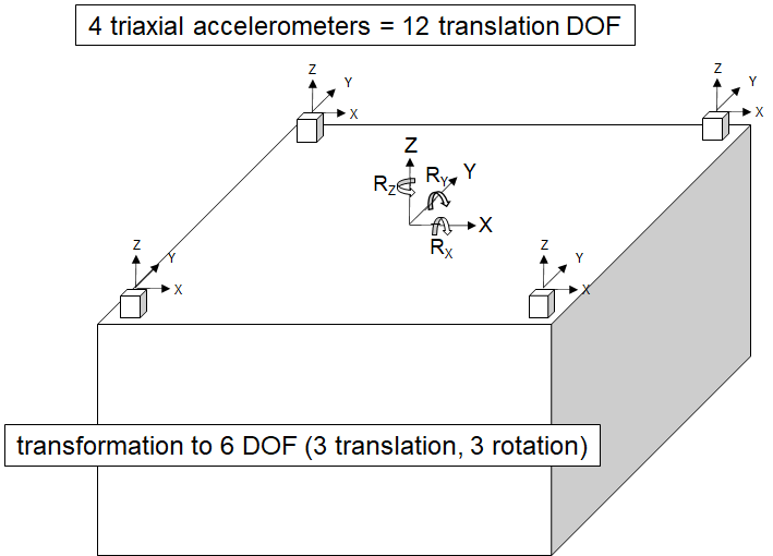
Degree of Freedom View
The 800 Series Controller numerically breaks down the test structure into controllable degrees of freedom, including rigid body DoFs and mode shapes.
- In a 6DoF shaker table setup, these correspond to the 6 rigid body translations/rotations and the mode shapes of the table/structure.
- In a modal excitation configuration, these DoFs would correspond directly to the structure’s modes
Defining Which DoFs are Controlled
Not all degrees of freedom should be controlled at all frequencies, and the 800 series controller has various methods to avoid over driving your shakers to control DoFs that shouldn’t be controlled.
- The controller divides forces between the actuators evenly if more actuators than DoFs.
- Controlled DoFs can switch with frequency – In a modal test, different mode shapes can be controlled at different frequencies.
- Different #DoFs can be controlled at different frequencies within the same test.
- On a shaker table, this allows control of the translations/rotations at low frequencies and also controlling mode shapes at higher frequencies.
Impedance Matched Multi-Axis Testing (IMMAT)
IMMAT is the cutting edge of vibration and structural testing, and still an active area of research led by top government research labs around the world. In IMMAT testing, the goal is to reproduce the dynamic environment experienced by the Device Under Test (DUT) as accurately as possible – to reproduce the exact deformations the DUT sees in the field. IMMAT does this by using several smaller/modal shakers connected to the test article with stingers; rather than the traditional method of placing the DUT on a large shaker table.
Traditional single axis vibration testing methods reproduce a given profile (such as a Random Power Spectral Density) at a single point; or the average of several points. The test is run in a single axis at a time, which in itself is unrealistic. But perhaps more importantly, the control point(s) conforming to a field-representative profile does not guarantee the whole DUT will see the same vibrations in the lab as it sees in the field.
The reasons for this are three-fold: First, the field vibration environment is multi-axis and the traditional shaker table operates in one axis at a time. Second, the mechanical coupling between the test article and the fixturing/shaker (the impedance) is generally very different from the impedance when the test article is in-situ. Third, the force inputs exciting the DUT are also generally not the same in the lab as they are in the field.
To perform an IMMAT style test, field data must be recorded at several key locations on the DUT; which will then be used or reduced into the profile that will be used in the lab. Back in the lab, the DUT must be “impedance-matched” to its field configuration.
The term “impedance matched” refers to the matching of the impedance characteristics between the test equipment (fixturing/actuators) and the structure being tested.
Impedance matching ensures that the test equipment can effectively reproduce the exact vibrations seen in the field back in the lab. Another way to think about this is that the modal characteristics of the DUT in its field and lab configurations must be matched – the modes of the DUT should be at the same frequencies. Once the impedance has been sufficiently matched, the shakers and excitation points must be selected.
The vibration controller is a critical component of the IMMAT test. It must be able to take the complex environment measured in the field (either time histories or a Spectral Density Matrix reduced from them) and reproduce them in the lab. Furthermore, the Data Physics Multi-Axis Vibration Controller has several features which are critical to running a successful IMMAT test; such as easy importing of the complex IMMAT profile data or algorithms to better control the various modes of the structure.
IMMAT Case Study
In their paper “Balancing Impedance and Controllability in Response Reconstruction”, the authors (Prof. Matthew Allen, Dr. Washington J. DeLima, et. al) present their findings trying to quantify the degree of impedance matching required between the lab and field for a successful IMMAT test.
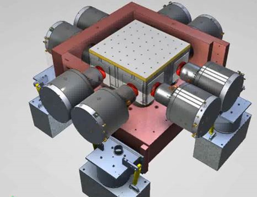
In the experiment, a subcomponent and its “Transmission Structure” (mounting fixture) were instrumented and data recorded while mounted on a sounding rocket being launched. Back in the lab, the subcomponent was reconstructed along with different transmission structures – each with a varying degree of similarity to the flight configuration. One such configuration can be seen in the below image. The Subcomponent is the smallest plate visible towards the top of the image; and the plates below are the transmission structure. Various shakers can be seen connected to the structure, with stingers directly to the transmission structure; as well as mounted directly to the transmission structure.

In their experiments, they discovered that there are not increasing returns when trying to match impedance between the field and lab configurations by just using more of the operational structure in the lab configuration – that is the best reproduction of the field environment may not come from the setup which best matched the impedance of the transmission structure.
In the paper, the authors discuss the effectiveness of the Data Physics Controller in controlling a complex IMMAT test like this. The Data Physics Controller has DoF-reduction algorithms which dramatically and intelligently reduce the drive requirements to run a IMMAT test, while minimally reducing the controllability. The authors experimented with these settings during their project, as they are required to ensure the shakers are not overdriven. They incorporated these control parameters to their simulation code as it is the most effective method to minimize the shaker force requirements; which ultimately reduce equipment costs and make IMMAT testing more feasible.
Controlling Out Modes of a 6DoF Shaker Table
The Team Tensor 6DoF table has 12 electrodynamic actuators (4 in each axis) for full 6DoF control. At low frequencies, the 800 Series controller uses the additional actuators by distributing the force equally; at high frequencies, it can use them to counteract table resonances and keep the table rigid to a higher frequency.
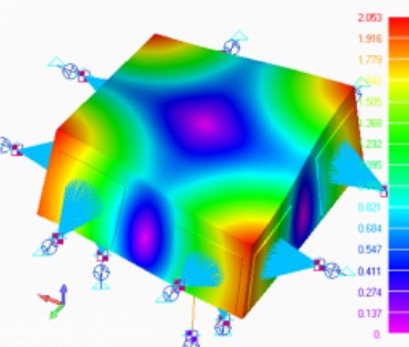
The first mode shape of the Tensor table is shown to the right.
The Tensor’s actuators can be actively controlled to fight the mode shapes of the table and keep the table rigid. The 800 Series controller can be instructed to do this by either defining the mode shape(s) explicitly and nulling them; or by defining a profile which implicitly requires modal deformation to be eliminated.
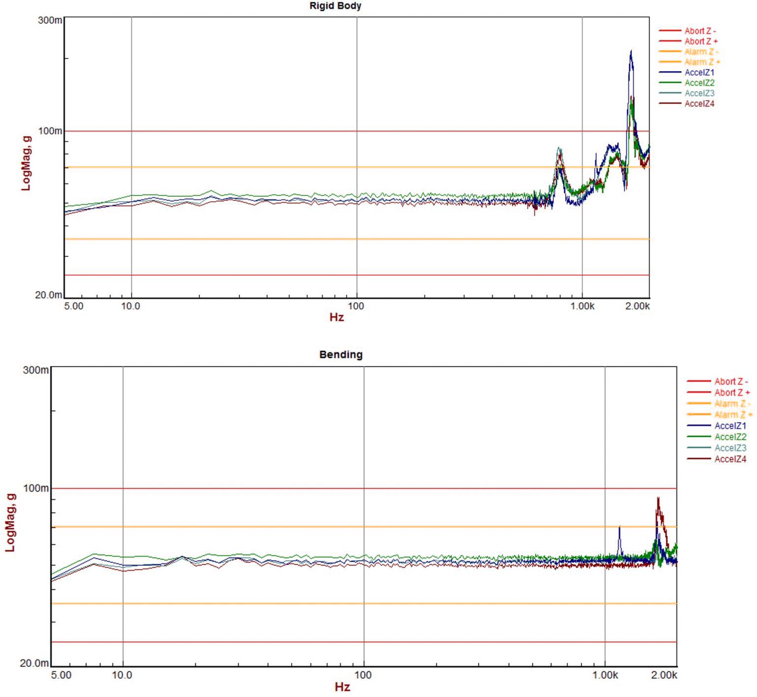
With control accelerometers at the corner of the table, the Tensor was run without controlling any modes (only controlling rigid body translations/rotations); and the results are shown on the top right plot. The first and second resonances are clearly seen in the 800-2000Hz range.