
Manufacturing shaker systems involves more than just selling the shaker. It involves understanding the accessories and options required for the user’s application. Most importantly, the shaker system needs to be able to perform the user’s vibration tests. A wide variety of optional items are offered to configure countless different configurations of vibration test systems. Thorough knowledge of the application requirements will aid in properly configuring a system.
The following descriptions apply to most of the shaker systems offered by Data Physics.
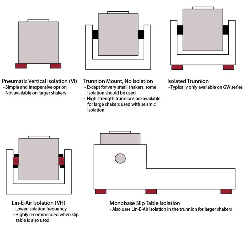
Isolation
Pneumatic isolation is not included with the standard shaker or Monobase systems. It is optional and there are several types of isolation:
Neoprene Rubber Pad Isolation: This option is the most basic type of isolation and can isolate as low as 20 Hz. These pads are provided as the standard method of isolation with Monobase systems.
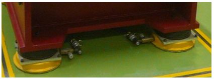
Pneumatic Isolation Mounts: Pneumatic isolation mounts are mounted under the shaker, trunnion, or monobase and are effective to 5 Hz. Data Physics uses isolation mounts that have steel reinforced side walls for reduced lateral movement.
Lin-E-Air Trunnion Isolation: Lin-E-Air isolation is an extremely effective method to isolate the shaker down to approximately 2 Hz. The isolation uses double pneumatic air bags built into the trunnion. Lin-E-Air is also very effective for horizontal isolation. All monobases for shakers 8,000 lbf (35 kN) and larger include Lin-E-Air isolation mounting.
Seismic Isolation: For very large test articles, seismic isolation may be required to have a proper reaction mass. In this instance, the shaker needs to be directly coupled to the seismic mass through a solid trunnion and the seismic mass must be isolated from the ground. A shaker mounted solidly to a seismic mass requires a robust trunnion assembly. It must be designed to be able to withstand all of the forces from the test system. Data Physics can provide guidance and even design services for seismic isolation.
Opto-Pneumatic Load Centering
The OPCS option for LE series shakers and the ALS option for some GW series shakers both allow automatic centering of the armature using internal pneumatic support when the system is in the vertical position. This option helps to ensure that the shaker is in the center position for shock testing. Additionally, this option is recommended if it is intended that a test article or head expander be left on the shaker when not in test. Otherwise, flexure warp can result over time. Users can always manually adjust the positioning.
Mobility Options for Electrodynamic Shakers
While it is almost always preferable to leave the electrodynamic shaker stationary, there are options available to easily reposition the shaker.
Combined thermal testing is a common application requiring mobile shakers. With larger shakers, however, it is still preferable to leave the shaker stationary and move the environmental chamber.
Historically, V-Groove wheels and rail guidance were used to move shakers under chambers. The guidance system placed the shaker in the center of the chamber in a repeatable fashion.
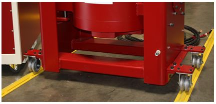
Air glides are another possibility for positioning both large and small shakers. While lacking guidance, they easily move the largest shaker.
Additionally, wheels or castors can be fitted to GW series shakers for mobility.
Packaging and Shipment Preparation for Shaker Systems
All shakers require packaging and shipping preparation from the factory. In addition to the shaker system, head expanders, slip tables, and monobase slip table assemblies all require packaging to be added.
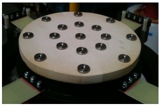
Inserts
Standard head expanders and slip tables will not have any threaded inserts in them. Data Physics allows flexibility in the insert pattern. Customers may choose a standard insert pattern, a custom insert pattern, or no insert pattern at all.
If adding a standard pattern, the pattern is centered and the inserts need to be purchased for the entire pattern. For instance, if it is a 9 x 9 pattern, 81 inserts need to be added. In some cases adding the shaker armature pattern to the slip plate is beneficial.
Specifying inserts also involves specifying thread size. On the same note, nearly every SignalForce shaker can be made with SAE or metric threads, and that thread type has to be specified when ordering.
Thermal Barriers
It is generally recommended that thermal barriers be used on the shaker armature during any thermal testing, even if using a head expander and slip table. Armature thermal barriers are priced inclusive of any required raised inserts.
Thermal barriers for head expanders and slip tables are configured differently. In the case of the standard G10 barriers found in the pricelist, these flat barriers attach directly to a flat head expander or slip table and allow direct mounting. Fixing holes (thermal plugs) are required in thermal barriers over counter-bored holes. There must be an equal number of fixing holes added as there are armature mounting locations and bearing mounting holes.
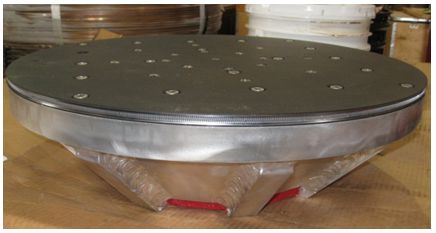
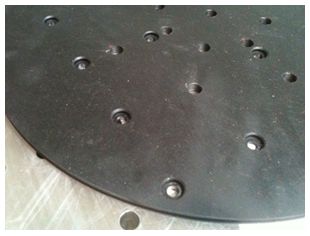
The G10 barriers cover temperatures from -40° C to + 120°. Other materials are available for wider temperature ranges. These materials often require raised inserts in addition to the thermal barrier because they are made from softer silicon based material.
It is almost always recommended to have a separate thermal barrier for the head expander and slip plate due to the labor involved in switching them.
Bearing Guidance for Slip Tables
Any required guidance for a slip table is also separately specified. An overturning moment check will provide the information required to size the type and number of bearings needed for overturning moment restraint. Slip tables can be configured with standard linear bearings and hydrostatic bearings to restrain moments. Overturning moments will be discussed in more detail in next issue of the Insider.
Drive Adapter
Larger tests using slip tables should incorporate a drive adapter, sometimes referred to as a “bull nose”. The general rules of thumb are to use a drive adapter on tests with masses greater than 100 lbs (45 kg) when a high restraint bearing system is used or if the force required is 18,000 lbf (80 kN) or higher. The article “When to Select an Optional Welded Magnesium Drive Adapter” reviews when to select a drive adapter.
Cable Length
If the shaker and amplifier are going to be further apart than the standard cable length provided with the system, then extra cable length must be ordered. Consult the factory for the price per foot or meter and be aware that extra length of cable will de-rate the shaker available force.
Extra Cooling Hose Length
The standard length of cooling hose for air cooled shakers is 3 m (10 ft). Most often, the customer will acquire additional cooling hose or ducting on their own, but this can also be provided at additional cost.
NOTE: It is important to check the distance that the customer plans to run the ducting, and to allow us to provide advice on how they can duct the air without a loss in performance. Elbows, bends, and long distance runs will all increase the resistance of airflow and could limit the performance of the shaker.
Head Expander Guidance
If the head expander has a load that is greater than the shaker’s load capacity or if it is larger than 2.5 times the diameter of the armature’s outer bolt circle, then an external guidance system will be required. Some tests may also have a heavy load that is required to be off-center. These situations may also require guidance.
Guided head expander systems are often custom designed for the shaker and head expander combination. The frame can include flexure guidance, load support, over travel limits, and even mechanisms to allow the shaker to rotate.
CE Marking
CE Marking is not standard. If CE marking is required, it must be added as an option.
Shaker System Checklist (Typical)
Shaker System
- Thermal Barrier for shaker armature (if required)
- Opto-Pneumatic load centering (optional)
- Mobility options (if required)
- Extra cabling (if required)
- Extra ducting (if required)
- Packaging and Shipping Preparation, Shaker System
- Head Expander (if required)
- Inserts based on hole pattern
- Thermal barrier (if required)
- Thermal fixing holes based on hole pattern
- Packaging and Shipping Preparation Head Expander
- Mounting: Pneumatic Isolation, Trunnion, or Monobase Slip Table (if required)
- Pneumatic floor isolation (if required)
- Drive adapter (if required)
- Guide bearings (if required)
- Inserts based on hole pattern
- Thermal barrier (if required)
- Thermal fixing holes based on hole pattern
- Packaging and Shipping Preparation, Monobase Slip Table