This article, and the upcoming sequels, will take a fresh look at how to correctly select the right size electrodynamic shaker for each application. Reviewing this topic should help those using shakers refresh their understanding of proper shaker sizing. Incorrectly sizing shakers or sizing by simple rules of thumb can result in customers paying too much for an oversized shaker or being unable to run their tests due to an undersized shaker.
Shaker sizing is based on evaluating the force, acceleration, velocity, and displacement available in the shaker versus what is required by the test or tests. Often users of shakers do not consider anything beyond force, but force is almost always only the starting point of shaker selection.
Evaluating Force
The simple equation given by Newton’s second law is the basis for evaluating force:
F = mA
This equation can be solved for acceleration, mass, or force depending on the known variables. Most often, it is solved to determine the required force. When solving this equation, one needs to keep in mind units. Conveniently, the units work without conversion factors for imperial units: lbf = lbm *g (in either peak or rms).
Force is calculated as above. It is universally recommended by all reputable electrodynamic shaker manufacturers that day-to-day operation of shakers is at or below 80% of peak force of a shaker.
Mass is the total moving mass. This includes the armature mass of the shaker, any accessories (slip tables, bearings, head expanders, and thermal barriers), fixtures, and test articles. Because the armature mass is included, the total moving mass is dependent on the selected shaker.
Acceleration is often provided by the test profile. The more simple case is sine, for sine sweeps, the acceleration is the peak level of the sine wave throughout the profile. For random tests it will be the RMS level of the entire random profile to 2000 Hz.
Because a shaker’s maximum random force rating is based on a 2000Hz bandwidth, for profiles less than 2000 Hz, the available force must be de-rated (remember RMS value is the area under the PSD curve across the entire bandwidth). The de-rating factor is equal to the square root of the ratio between the actual bandwidth and the rated bandwidth as follows:

Evaluating Acceleration, Velocity, and Displacement
Shakers may have acceleration limits that are based on capacity of the amplifier or structural integrity of the armature. When sizing the shaker for a sine test, simply check to make sure the peaks do not exceed the published maximum peak values.
For high amplitude random tests, it is also advisable to consider the acceleration peak limits – particularly for narrow band testing. The acceleration peaks will depend on the sigma value of the random generation. Because random is statistical in nature, these high sigma peaks could have a narrow width or wide width, effectively negating capacitance gains. The simplest approach is to evaluate the acceleration peaks at the sigma value times the rms acceleration level. Conservatively, this peak acceleration value should be compared with the armature sine acceleration limits.
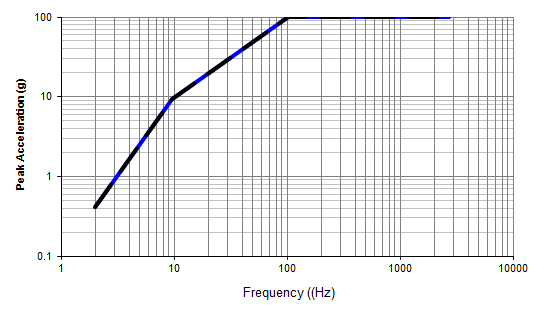
The same concept applies for velocity and displacement. The shaker has limits on both these and they are variable with the frequency of the sine wave. Lower frequency sine waves can run into velocity and displacement limits. The nomograph of shaker peak performance below illustrates this. In this specific example, the shaker is limited by displacement from 2 Hz to 10 Hz (roughly), by velocity from 10 Hz to 100 Hz, and by acceleration from 100 Hz to 2000 Hz. These performance limits will change with load, but the overall profile cannot exceed the maximum capabilities of the shaker.

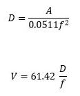
Rarely does a sine test profile provide acceleration, velocity, and displacement levels. The relationship between these values is based on sinusoidal wave properties, and can be summarized as follows:

A is acceleration in g pk
D is displacement in inches pk-pk (divide by 39.39 for meters pk-pk)
V is acceleration in in/s pk (multiply by 0.0254 for m/s pk)
The displacement capabilities of the shaker at low frequency can be further reduced by the type of shaker isolation, and should be considered if the displacement requirement is close to the shaker limits. Most shakers are isolated with low frequency pneumatic isolators. These isolators absorb some displacement due to the reaction force and consequently limit the total stroke of the shaker. The reduction in displacement is simply a ratio of the total mass moving on the isolation and the moving mass of the system:

Due to the broadband nature of random testing, random profiles rarely require additional checks. Low frequency random tests, however, do have the same displacement limitations. This limit should be considered at frequencies lower than 10 Hz. To evaluate the feasibility of running a specific test, the sigma peak value can be used to determine displacement limits at the lowest frequency of the test and compared with the limits for a low frequency sine tone.
Fortunately, shaker manufacturers develop tools to size shakers so that these calculations do not need to be done manually in every case. However, understanding these limitations and the sizing process allows sales engineers and shaker users to know what information is required for proper evaluation.

